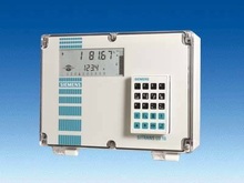
Преобразователь ультразвукового расходомера - Непрерывное измерение |
Introduction
Ultrasonic measurement is based on the speed of sound. Sound can be used as a measurement tool because there is a measurable time lapse between sound generation and the "hearing" of the sound. This time lapse is then converted into usable information. Ultrasonic sensing equipment generates a sound above 20 000 Hz and then interprets the time lapse of the returned echo. The transducer creates the sound and senses the echo and then a transceiver interprets the sound and converts it into information.
Siemens Milltronics ultrasonic units include Sonic Intelligence, a patented signal processing technology. Using unique algorithms, Sonic Intelligence differentiates between true echoes from the material and false echoes from obstructions or electrical noise, providing intelligent processing of echo profiles.
Typical System
Ultrasonic level measurement requires two components: one to generate the sound and catch the echo (transducer) and one to interpret the data and derive a measurement (transceiver). Even though some ultrasonic instruments combine the components in one unit, the individual functionality remains distinct. The measurement output is communicated to the unit, PLCs or PCs for process control.
Principle of Operation
A piezoelectric crystal inside the transducer converts an electrical signal into sound energy, firing a burst into the air which travels to the target, and then is reflected back to the transducer. The transducer then acts as a receiving device and converts the sonic energy back into an electrical signal. An electronic signal processor analyzes the return echo and calculates the distance between the transducer and the target. The time lapse between firing the sound burst and receiving the return echo is directly proportional to the distance between the transducer and the material in the vessel. This basic principle lies at the heart of the ultrasonic measurement technology and is illustrated in the equation: Distance = (Velocity of Sound x Time) / 2. |
Область применения

Ultrasonics Application Data Sheet |
Способ действияCommon Terms
Attenuation
Denotes a decrease in signal magnitude in transmission from one point to another. Attenuation may be expressed as a scalar ratio of the input magnitude to the output magnitude or in decibels.
Beam angle
The diameter of a conical boundary centered around the axis of transmission when the power (radiating perpendicular to the transducer face on the axis of transmission) is reduced by half
(-3 dB).
Blanking distance
Specified zone extending downward from the transducer face in which received echoes are ignored by the transceiver. Blanking distance ignores echoes from ringing.
Echo confidence
The recognition of the validity of the echo as industry level. A measure of echo reliability.
Ringing
The inherent nature of the transducer to continue vibrating after the transmit pulse has ceased; the decay of the transmit pulse.
Transducer/Transceiver
A transducer provides the initial ultrasonic pulse and receives its echo. An ultrasonic transducer amplifies the sound wave created by the piezoelectric crystal and transmits that sound wave to the face of the transducer while at the same time dampening the sound wave from the other sides of the crystal.
Transceivers analyze the echo from the transducer to determine the required measurement. |
Технические данныеUltrasonics Controller Selection Guide
|
Criteria
|
SITRANS
Probe LU
|
HydroRanger
200
|
MultiRanger
100/200
|
SITRANS LUC500
|
SITRANS LU
|
OCM III
|
|
Range
|
6 m (20 ft) or
12 m (40 ft)
|
15 m (50 ft) transducer and application dependent
|
15 m (50 ft) transducer and application dependent
|
15 m (50 ft) transducer and application dependent
|
60 m (200 ft) transducer and application dependent
|
3 m (10 ft)
|
|
Typical applications
|
chemical storage vessels, filter beds, liquid storage vessels
|
wet wells, flumes/weirs, bar screen control
|
wet wells, flumes/weirs, bar screen control, hoppers, chemical storage, liquid storage, crusher bins, dry solids storage
|
wet well/lift station control, weirs/flumes, open channels
|
chemical storage, liquid storage, bulk solids storage (sugar, flour bins, grains, cereals), plastic pellets
|
open channel measurement
|
|
Output
|
HART model: 4 to 20 mA/HART
PROFIBUS PA model: PROFIBUS
|
6 relays standard, two 4 to 20 mA outputs (isolated)‘
|
3 relays standard
6 relays (option)
Two 4 to 20 mA outputs (isolated)
|
5 relays, 4 to 20 mA (option)
|
4 relays (LU 01, LU 02)
Up to 40 relays (LU 10)
4 to 20 mA isolated
|
3 relays, 4 to 20 mA
|
|
Communications
|
HART or PROFIBUS PA
Options:
- SIMATIC PDM for remote configuration and diagnostics
|
Built-in Modbus RTU/ASCII via RS-485
Options:
- SIMATIC PDM
- SmartLinx (PROFIBUS DP, Allen-Bradley Remote I/O, DeviceNet)
|
Built-in Modbus RTU or ASCII via RS-485
Options:
- SIMATIC PDM
- Smartlinx (PROFIBUS DP, Allen-Bradley Remote I/O, DeviceNet)
|
Telemetry capability with Modbus RTU/ASCII via RS-232/RS-485
Options:
- SIMATIC PDM
- SmartLinx (PROFIBUS DP, Allen-Bradley Remote I/O, DeviceNet)
- ECT EnviroRanger Tool software
|
Dolphin, RS-232/RS-485 (LU 01, LU 02)
Dolphin via infrared (LU 10)
Options:
- SmartLinx (PROFIBUS DP, Allen-Bradley Remote I/O, DeviceNet)
|
Via RS-232
Options:
|
|
Power Specifications
|
HART: 4 to 20 mA, 24 V DC nominal, max. 550 ohm,
30 V DC max.
PROFIBUS PA: 12, 13, 15, or 20 mA, dependent on programming
|
AC version: 100 to 230 V AC ±15%, 50/60 Hz, 36 VA/17 W
DC version: 12 to 30 V DC, 20 W
|
AC version: 100 to 230 V AC ±15%, 50/60 Hz, 36 VA/17 W
DC version: 12 to 30 V DC, 20 W
|
AC version: 100 to 230 V AC ±15%, 50/60 Hz, 30 VA/17 W
DC version: 12 to
30 V DC, 20 W
|
LU 01, LU 02:
AC version: 100/115/200/230 V AC
DC version: 18 to 30 V DC, 25 W
LU 10: 100/115/200/ 230 V AC
|
100/115/200/230 V AC, ±15%, 50/60 Hz, 15 VA
and/or
9 to 30 V DC,
8 W
|
|
Approvals
|
CE, CSANRTL/C, FM, ATEX, FCC, R&TTE, Industry Canada
|
CE, CSANRTL/C, UL Listed, FM
|
CE, CSANRTL/C, UL Listed, FM
|
CE, CSANRTL/C, UL Listed
|
CE, CSANRTL/C, FM, Lloyd’s Register
|
CE, CSANRTL/C, FM
|
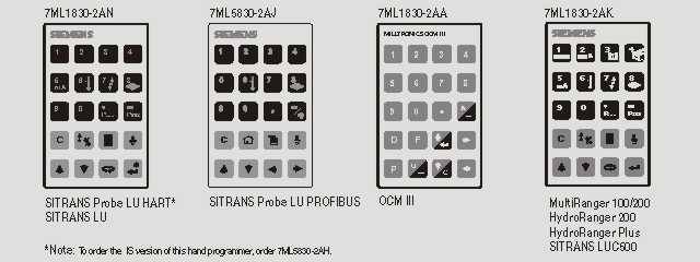
Handheld Programmer Selection Guide | |
|


