ФункцииIn contrast to almost all other gases, oxygen is paramagnetic. This property is utilized as the measuring principle by the OXYMAT 61 gas analyzers.
Oxygen molecules in an inhomogeneous magnetic field are drawn in the direction of increased field strength due to their paramagnetism. When two gases with different oxygen concentrations meet in a magnetic field, a pressure difference is produced between them.
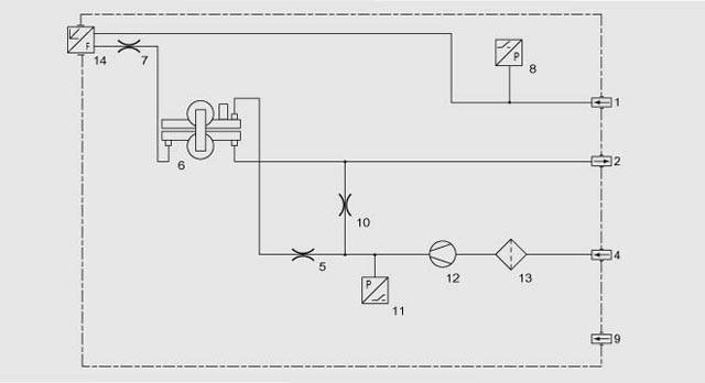
In the case of OXYMAT 61, one gas (1) is a reference gas (N2, O2 or air), the other is the sample gas (5). The reference gas is introduced into the sample chamber (6) through two channels (3). One of these reference gas streams meets the sample gas within the area of a magnetic field (7). Because the two channels are connected, the pressure, which is proportional to the oxygen concentration, causes a cross flow. This flow is converted into an electric signal by a microflow sensor (4).
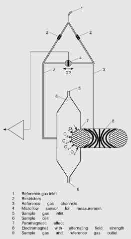
OXYMAT 61, mode of operation
The microflow sensor consists of two nickel grids heated to approx. 120 ºC which form a Wheatstone bridge together with two supplementary resistors. The pulsating flow results in a change in the resistance of the Ni grids. This results in a bridge offset which depends on the oxygen concentration in the sample gas.
Because the microflow sensor is located in the reference gas stream, the measurement is not influenced by the thermal conductivity, the specific heat or the internal friction of the sample gas. This also provides a high degree of corrosion resistance because the flow sensor is not exposed to the direct influence of the sample gas.
By using a magnetic field with alternating strength (8), the effect of the background flow in the microflow sensor is not detected, and the measurement is thus independent of the instrument orientation.
The sample cell is directly in the sample path and has a small volume. The microflow sensor thus responds quickly, resulting in a very short response time for the OXYMAT 61.
Note
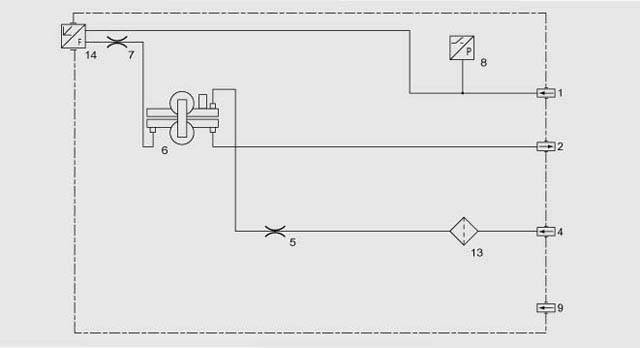
The sample gas needs to be free of dust. Condensate in the cells must be avoided. That is why the most measuring tasks require an appropriate gas preparation.
Special characteristics
- Four freely-parameterizable measuring ranges, also with zero offset, all measuring ranges linear
- Electrically isolated signal output selectable as 0/2/4 to 20 mA (also inverted)
- Autoranging or manual range switching possible; remote switching is also possible
- Storage of measured values possible during calibration
- Time constants selectable within wide limits (static/dynamic noise suppression); i.e. the response time of the analyzer can be matched to the respective application
- Simple handling using menu-based operation
- Low long-term drift
- Two operation levels with separate access code to prevent unintentional and unauthorized inputs
- Automatic range calibration can be parameterized
- Operation based on NAMUR Recommendation
- Monitoring of sample gas (option)
- Customer-specific analyzer options such as e.g.:
- Customer acceptance
- TAG labels
- Drift recording
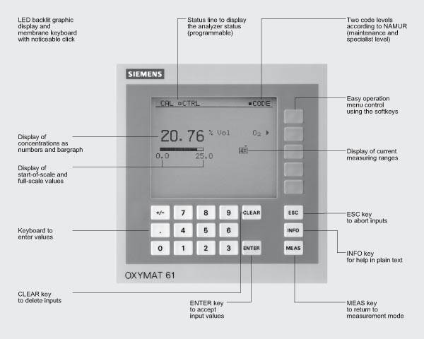
- Simple handling using a digital membrane keyboard and menu-based operation
- Short response time
- Reference gas supply external (N2, O2 or air, approx. 3000 hPa) or via an integrated reference gas pump (ambient air, approx. 100 hPa)
- Monitoring of reference gas with reference gas connection 3000 to 4000 hPa
- Different smallest spans, depending on version 2.0% or 5.0% O2
- Internal pressure sensor to correct sample gas variations.
Correction of zero error / Cross interferences
|
Residual gas
(concentration 100 % v/v)
|
Zero deviation
in % v/v O2 absolute
|
|
Residual gas
(concentration 100 % v/v)
|
Zero deviation
in % v/v O2 absolute
|
|
Organic gases
|
|
|
Inert gases
|
|
|
Acetic acid CH3COOH
|
-0.64
|
|
Argon Ar
|
-0.25
|
|
Acetylene C2H2
|
-0.29
|
|
Helium He
|
+0.33
|
|
1,2 butadiene C4H6
|
-0.65
|
|
Krypton Kr
|
-0.55
|
|
1,3 butadiene C4H6
|
-0.49
|
|
Neon Ne
|
+0.17
|
|
iso-butane C4H10
|
-1.30
|
|
Xenon Xe
|
-1.05
|
|
n-butane C4H10
|
-1.26
|
|
|
|
|
1-butene C4H6
|
-0.96
|
|
Anorganic gases
|
|
|
iso-butene C4H8
|
-1.06
|
|
Ammonia NH3
|
-0.20
|
|
Cyclo-hexane C6H12
|
-1.84
|
|
Carbon dioxide CO2
|
-0.30
|
|
Dichlorodifluoromethane (R12) CCl2F2
|
-1.32
|
|
Carbon monoxide CO
|
+0.07
|
|
Ethane C2H6
|
-0.49
|
|
Chlorine Cl2
|
-0.94
|
|
Ethylene C2H4
|
-0.22
|
|
Dinitrogen monoxide N2O
|
-0.23
|
|
n-heptane C7H16
|
-2.4
|
|
Hydrogen H2
|
+0.26
|
|
n-hexane C6H14
|
-2.02
|
|
Hydrogen bromide HBr
|
-0.76
|
|
Methane CH4
|
-0.18
|
|
Hydrogen chloride HCl
|
-0.35
|
|
Methanol CH3OH
|
-0.31
|
|
Hydrogen fluoride HF
|
-0.10
|
|
n-octane C8H18
|
-2.78
|
|
Hydrogen iodide HI
|
-1.19
|
|
n-pentane C5H12
|
-1.68
|
|
Hydrogen sulphide H2S
|
-0.44
|
|
iso-pentane C5H12
|
-1.49
|
|
Oxygen O2
|
+100
|
|
Propane C3H8
|
-0.87
|
|
Nitrogen N2
|
0.00
|
|
Propylene C3H6
|
-0.64
|
|
Nitrogen dioxide NO2
|
+20.00
|
|
Trichlorofluoromethane (R11) CCl3F
|
-1.63
|
|
Nitrogen oxide NO
|
+42.94
|
|
Vinyl chloride C2H3Cl
|
-0.77
|
|
Sulphur dioxide SO2
|
-0.20
|
|
Vinyl fluoride C2H3F
|
-0.55
|
|
Sulphur hexafluoride SF6
|
-1.05
|
|
1,1 vinylidene chloride C2H2Cl2
|
-1.22
|
|
Water H2O
|
-0.03
|
Zero error due to diamagnetism or paramagnetism of residual gases with nitrogen as the reference gas at 60 °C and 1000 hPa absolute (according to IEC 1207/3)
Conversion to other temperatures:
The zero errors mentionned in the table must be multiplied with a correction factor (k):
- with diamagnetic gases: k = 333 K / (θ [°C] + 273 K)
- with paramagnetic gases: k = [333 K / (θ [°C] + 273 K)]2
(all diamagnetic gases have a negative zero error).
Reference gases
|
Measuring range
|
Recommended reference gas
|
Reference gas connection pressure
|
Remarks
|
|
0 to . . . % v/v O2
|
N2
|
|
The reference gas flow is set automatically to 5 to 10 ml/min
|
|
. . . to 100% v/v O2 (suppressed zero with full-scale value 100% v/v O2)
|
O2
|
3000 to 4000 hPa absolute, reference gas from gas cylinder
|
|
Around 21% v/v O2 (suppressed zero with 21% v/v O2 within the span)
|
Air
|
Atmospheric air pressure with internal reference gas pump
|
|