SIEMENS / Каталог продукции департамента "Автоматизация и Приводы" Телефон: +7 (495) 259-08-22
Электронная почта: info@aqad.ru
 
Расширенный поиск Сделать запрос
Каталог продуктов Siemens IA/DT
 Автоматизация процесса
  Контрольно-измерительные приборы
  Программное обеспечение
  Системы управления процессом
  Технологии взвешивания
  Соединения и коннекторы Profibus PA
  Коммуникации и программное обеспечение
  Анализаторы процесса
          Приборы для анализа процесса
                  Непрерывные анализаторы газов, эктрактивные
                   ULTRAMAT 23
                   ULTRAMAT 6
                   ULTRAMAT/OXYMAT 6
                   OXYMAT 6
                   OXYMAT 61
                   CALOMAT 6
                    

Общее

                    19"" - корпус
                    Полевой корпус
                    Документация
                    Планирование запасных частей
                   FIDAMAT 6
                   Введение
                  Непрерывный газовый анализ, in-situ
                  Analytical Application Sets
                  Введение
                  Промышленные газовые хроматографы
 Блоки питания
 Технология безопасности
 Системные решения и продукты для отраслей
 Приводная техника
 Техника автоматизации
 Электроустановочная техника
 Низковольтная коммутационная техника
 ... и все, что Вам еще необходимо
 Специализированные сенсоры
 Коммуникации и сети
 Сервис
 Случайная рубрика

Общее - CALOMAT 6

Общее - CALOMAT 6

The CALOMAT 6 gas analyzer is primarily used for quantitative determination of H2 or He in binary or quasi-binary gas mixtures.

Concentrations of other gases can also be measured if their thermal conductivities differ significantly from the residual gases like Ar, CO2, CH4, NH3.

19” unit and field unit

Особенности

  • Small T90 time due to micromechanical-produced Si sensor
  • Universally usable hardware base, high measuring range dynamic (e.g. 0 ... 1%, 0 ... 100%, 95...100% H2)
  • Integrated interfering gas correction, external calculation not required
  • Open interface architecture (RS 485, RS 232, PROFIBUS)
  • SIPROM GA network for maintenance and servicing information (option)
  • Electronics and physics: gas-tight isolation, purging is possible, IP65, high service life even in harsh environments
  • EEx(p) for zones 1 and 2 (according to 94/9/EC (ATEX 2G and ATEX 3G)), Class I Div 2 (CSA) Ex(n).

Область применения

  • Pure gas monitoring (0 ... 1% H2 in Ar)
  • Inert gas monitoring (0 ... 2% He in N2)
  • Hydroargon gas monitoring (0 ... 25% H2 in Ar)
  • Forming gas control (0 ... 25% H2 in N2)
  • Gas production:
    • 0 ... 2% He in N2
    • 0 ... 10% Ar in O2
  • Chemical applications:
    • 0 ... 2% H2 in NH3
    • 50 ... 70% H2 in N2
  • Wood gasification (0 ... 30% H2 in CO/CO2/CH4)
  • Blast furnace gas (0 ... 5% H2 in CO/CO2/CH4/N2)
  • Bessemer converter gas (0 ... 20% H2 in CO/CO2)
  • Monitoring equipment for hydrogen-cooled turbo-alternators:
    • 0 ... 100% CO2/Ar in air
    • 0 ... 100% H2 in CO2/Ar
    • 80 ... 100% H2 in air
  • Version to analyze flammable and non-flammable gases or vapors for use in hazardous areas (zone 1 and zone 2).

Special applications

Besides the standard combinations, special applications are available on request (e.g. higher sample gas pressure up to 2000 hPa absolute).

Дизайн

19“ unit

  • With 4 HU for installation
    • in swing frame
    • in cabinets, with or without slide rails
  • Front panel for service can be hinged down (laptop connection)
  • Internal gas paths: pipe made of stainless steel
  • Gas connections for sample gas input and output and for reference gas: stubs, pipe diameter 6 mm or 1/4".

Field unit

  • Two-door housing (IP65) with gas-tight separation of analyzer and electronics section
  • Sections can be purged separately
  • Gas path and pipe couplings made of stainless steel (type No. 1.4571)
  • Purging gas connections: pipe diameter 10 mm or 3/8"
  • Gas connections for sample gas input and output and for reference gas: clamping ring connection for pipe diameter 6 mm or ¼“.

Display and control panel

  • Large LCD panel for simultaneous display of:
    • Measured value (digital and analog displays)
    • Status line
    • Measuring ranges
  • Contrast of LCD panel adjustable using menu
  • Permanent LED backlighting
  • Washable membrane keyboard/front panel with five softkeys
  • Menu-based operation for configuration, test functions and calibration
  • User help in plain text
  • Graphic display of concentration trend; programmable time intervals
  • Operating software in two languages: German/English, English/Spanish, French/English, Spanish/English, Italian/English.

Inputs and outputs

  • One analog output
  • Two analog inputs programmable (e.g. for correction of cross interferences or external pressure sensor)
  • Six binary inputs freely configurable (e.g. for range switching, processing external signals from sample conditioning)
  • Six relay outputs freely configurable (e.g. for failure, maintenance request, limit alarm, external solenoid valves)
  • Extension with eight additional binary inputs and eight additional relay outputs (e.g. for automatic calibration with up to four calibration gases).

Communication

  • RS 485 present in basic unit (connection at the rear, with 19“ unit also possibility of connection behind the front plate).

Options

  • RS 485/RS 232 converter
  • RS 485/Ethernet converter
  • Linking to networks via PROFIBUS DP/PA interface
  • SIPROM GA software as service and maintenance tool.

CALOMAT 6, membrane keyboard and graphic display

Versions – Wetted parts

Gas path

19“ unit

Field unit

Field unit Ex

With pipes

Bushing

SS, type No. 1.4571


Pipe

SS, type No. 1.4571


Sample cell body

SS, type No. 1.4571


O-rings

FFKM - Chemraz


Sensor

Si, SiOxNy, AU, epoxy resin, glass


Tightness

leakage < 1 μl/s


CALOMAT 6, 19“ unit, gas path

CALOMAT 6, field unit, gas path

Функции

Mode of operation

The measuring principle is based on the different thermal conductivity of gases.

The CALOMAT 6 sensor is a micromechanical-made Si chip with a measuring membrane and thin-film resistors.

The resistors are adjusted on a constant temperature. This requires an current intensity depending on the sample gas thermal conductivity. Further this „coarse value“ is electronically processed and used to calculate the gas concentration.

The sensor is located in a thermostatically-controlled stainless steel enclosure in order to prevent influences of ambient temperature changes.

To prevent the influences by the sample gas flow changes, the sensor is not placed in the main flow.

Note

The sample gas needs to be free of dust. Condensate (dew point of sample gas < ambient temperature) in the cells must be avoided. That is why the most measuring tasks require an appropriate gas preparation.

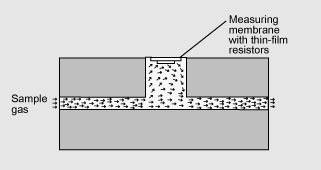
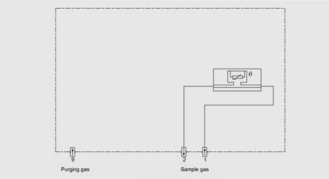
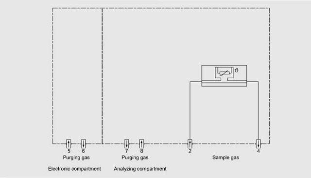
CALOMAT 6, mode of operation

Special characteristics

  • Four freely-progammable measuring ranges, also with zero offset, all measuring ranges linear
  • Smallest spans up to 1% H2 (with suppressed zero: 95 to 100% H2) possible
  • Electrically isolated analog output 0/2/4 to 20 mA (also inverted)
  • Autoranging or manual range switching possible; remote switching is also possible
  • Storage of measured values possible during calibration
  • Time constants selectable within wide limits (static/dynamic noise suppression); i.e. the response time oft he analyzer can be matched to the respective application
  • Short response time
  • Low long-term drift
  • Measuring point selection for up to 6 measuring points (can be parameterized)
  • Measuring range identification
  • Measuring point identification
  • External pressure sensor for correction of pressure variations in sample gas
  • Automatic range calibration can be parameterized
  • Operation based on NAMUR Recommendation
  • Two operation levels with separate access code to prevent unintentional and unauthorized inputs
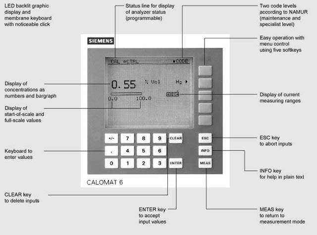
  • Simple handling using a numerical membrane keypad including operator prompting
  • Customer-specific analyzer options such as e.g.:
    • Customer acceptance
    • Tag labels
    • Drift recording
    • Clean for O2-Service.

Spans

The smallest and largest spans which are possible depend on the measured component (type of gas) as well as the respective application.

The smallest possible spans listed below refer to N2 as the residual gas. With other gases which have a larger/smaller thermal conductivity than N2, the smallest possible span is also larger/smaller.

Component

Smallest possible span

H2

0 ... 1% (95 ... 100%)

He

0 ... 2%

Ar

0 ... 10%

CO2

0 ... 20%

CH4

0 ... 15%

H2 in blast furnace gas

0 ... 10%

H2 in converter gas

0 ... 20%

H2 with wood gasification

0 ... 30%


Influence of interfering gases

Knowledge of the sample gas composition is necessary to determine the influence of residual gases with several interfering components.

The following table lists the zero offsets expressed in % H2 resulting from 10% residual gas (interfering gas) in each case.

Component

Zero offset

Ar

-1.28%

CH4

+1.59%

C2H6 (non-linear response)

-0.04%

C3H8

-0.80%

CO

-0.11%

CO2

-1.07%

He

+6.51%

H2O (non-linear response)

+1.58%

NH3 (non-linear response)

+1.3%

O2

-0.18%

SF6

-2.47%

SO2

-1.34%

Air (dry)

+0.5%


For residual gas concentrations differing from 10%, the correspondant multiple of the table value gives an acceptable approximation. This is valid for for residual gas concentrations up to 25% (dependent on gas type).

The thermal conductivity of most gas mixtures has a non-linear response. Even ambiguous results, such as e.g. with NH3/N2 mixtures, can occur within a specific concentration range.

In addition to a zero offset, it should also be noted that the gradient of the characteristic is influenced by the residual gas. However, this effect is negligible for most gases.

In case of correction of the influence of interfering gases with additional analyzers (ULTRAMAT 6/ULTRAMAT 23), the resulting measuring error can – depending on the application – amount up to 5% of the smallest measuring range of the application.

Example interfering gas correction

Specification of the interface cable

Characteristic impedance

100 ... 300 Ω, with a measuring frequency of > 100 kHz

Cable capacity

typ. < 60 pF/m

Wire section

> 0.22 mm2, corresp. AWG 23

Cable type

twisted pairs, 1 x 2 wire of cable section

Signal attenuation

max. 9 dB over the whole length

Screening

copper braid shield or braid shield and foil screen

Connection

pin 3 and pin 8


Bus terminating resistors

The pin 3-7 and 8-9 of the first and last connector of a bus cable have to be bridged (see figure).

Note

It is advisable to install a repeater on the device side in case of a cable length increasing 500 m or of high interferences.

Up to four components can be corrected via ELAN bus, a cross correction can be effected for up to two components via analog inlet.

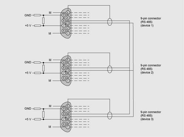
Bus cable with connector assignments