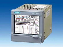
ENG: SIREC DM and SIREC DH - Цифровые дисплейные самописцы SIREC |
- Permits the recording of up to 16 analog inputs and 16 binary inputs (SIREC DM) or 32 analog inputs and 32 binary inputs (SIREC DH)
- Output on a color LC display (TFT)
- 5.5" with SIREC DM
- 12.1" with SIREC DH
- Storage of data on 1.44 Mbyte diskette or PCMCIA card (ATA flash type II)
- Ethernet interface as standard
- Data evaluation using the SIREC D-Viewer PC program (included in scope of delivery)
- Programming from the front panel or using the SIREC D-Manager PC program (option)
- Full network functionality (FTP, real-time Trendbus, Modbus) with the SIREC D Server PC program (option)
- Web server function
|
Область примененияThe SIREC DM/DH recorders are used to record and display electrical variables.
The measured data in the main memory are available on the display for direct observation of the trend. The measured data on the replaceable data memory are evaluated on a PC.
- The input variables can be freely adjusted within wide ranges. The unit is therefore suitable for almost all process engineering sectors.
- The binary inputs and binary outputs permit control of the unit or also the output of signals.
- The recorder can be connected to a PC via Ethernet to permit central acquisition of the measured data.
- Comprehensive mathematical functions are optionally available.
|
ДизайнIn housing for panel mounting;
front dimensions 144 x 144 mm (SIREC DM) or 300 x 300 mm (SIREC DH).
The units are operated and set using an input panel (keys and spinwheel) on the front panel.
The drives for data storage (diskette drive and slot for PCMCIA card) are located behind the display (SIREC DM) or behind a cover (SIREC DH) and are readily accessible. The PCMCIA cards are not included in the scope of delivery.
The type and quantity of measuring inputs and switching outputs/inputs depends on the order. The number of terminals can therefore vary depending on the configuration.
The electric connections are made at the rear of the recorder:
- Power supply connection: appliance plug for 90 to 250 V AC version
- Power supply connection: screw terminals for 24 V DC version
- Process signal connections: plug-in screw terminals
- Ethernet TCP/IP interface connection: 8-pin RJ45 connector
The signal inputs "Fast sampling" for the current ranges have an internal shunt (switch).
External shunts are required for the option "Universal card with high EMC". |
ФункцииThe process variables are measured, and displayed as trend curves, bargraphs or digital displays in various combinations.
The internal memory (4 Mbyte with SIREC DM, 8 Mbyte with SIREC DH) is operated as a ring buffer. The oldest data in each case are overwritten by the newest data.
The following versions are possible for data recording on diskette or PCMCIA card:
- Selective data storage per channel. Individual selection of storage method and rate
- Optional data compression using fuzzy logging mode (selectable per channel)
Display of measured data
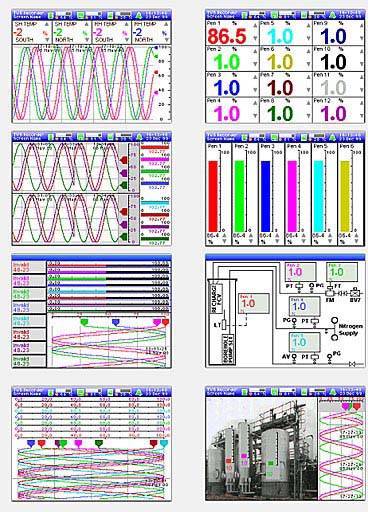
SIREC DM display modes
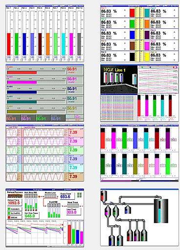
SIREC DH display modes
The display of the measured data can be freely adjusted within wide ranges, permitting:
- Analog trend display up to 12,000 mm/h
- Horizontal or vertical analog display
- Horizontal or vertical bargraph
- Detailed alarm and event reports
- Numerical display of values
- Event marking with I&C number, time and date
- Status line with date, time, occupation of RAM and diskette in percent
- Customized display and plant displays (SIREC DH)
Further important features
- Simple and fast configuration on the device or using software
- Operating menu in German, English, French, Italian, Spanish, Portuguese, Polish, Hungarian, Slovakian, Czech, Romanian, Turkish
- User-defined access coding with password protection. There are four access levels; up to 10 different passwords are possible.
- Enhanced security system ESS; with this option, the two SIREC DM/DH recorders comply with the requirements of FDA 21CFR Part 11
- Real-time clock with calendar function (with lithium backup battery, service life 10 years)
|
Технические данные
|
Inputs
|
|
|
Quantity
|
|
|
|
8, 12 or 16 input channels
|
|
|
24 or 32 input channels
|
|
Sampling rates
|
|
|
|
|
|
|
200 ms (5 Hz)
|
|
|
500 ms (2 Hz)
|
|
|
|
- mA, mV, thermocouples/PT100
|
500 ms (2 Hz)
|
|
Measured variables and measuring range limits
|
|
|
Transmitter power supply
|
|
|
|
18 ... 24 V; 1 A
|
|
|
18 ... 24 V; 0.2 A
|
|
Electrical isolation
|
100 V DC between the channels,
300 V DC between channels and ground
|
|
Input variables
|
|
|
|
± 1 V, ± 10 V
± 100 mV, ± 200 mV
|
|
|
± 10 mA, ± 20 mA
|
|
|
16 bits A/D converter (0.0015%)
|
|
Effects of ambient temperature
|
|
|
|
0.005%/°C
|
|
|
0.02%/°C
|
|
Input resistance, voltage inputs
|
> 1 MΩ
|
|
Current loop resistance
|
|
|
|
Internal, approx. 10 Ω ± 5%
|
|
|
With external 250 Ω shunt
|
|
Fast sampling card
|
|
|
Thermocouples
|
Temperature range
|
|
|
0 ... 2300 °C
|
|
|
-200 ... 0 °C
0 ... 1000 °C
|
|
|
-200 ... 0 °C
0 ... 1190 °C
|
|
|
-200 ... 0 °C
0 ... 1000 °C
1000 ... 1350 °C
|
|
|
-200 ... +900 °C
|
|
|
-200 ... 0 °C
0 ... 1300 °C
|
|
|
-200 ... 0 °C
0 ... 400 °C
|
|
|
1000 ... 2300 °C
|
|
|
-50 ... +1300 °C
|
|
|
-50 ... +600 °C
|
|
Resistance thermometers
|
Temperature range
|
|
|
-200 ... +650 °C
|
|
|
-200 ... +180 °C
|
|
|
-60 ... +180 °C
|
|
|
-80 ... +240 °C
|
|
Universal card
|
|
|
Thermocouples
|
Temperature range
|
|
|
0 ... 260 °C
260 ... 538 °C
538 ... 1820 °C
|
|
|
0 ... 316 °C
316 ... 1982 °C
1982 ... 2300 °C
|
|
|
-200 ... -130 °C
-130 ... +1000 °C
|
|
|
-18 ... +871 °C
|
|
|
-18 ... +1316 °C
|
|
|
-200 ... +900 °C
|
|
|
-18 ... 1300 °C
|
|
|
-18 ... +260 °C
260 ... 1704 °C
|
|
|
-18 ... +260 °C
260 ... 1704 °C
|
|
|
-184 ... +371 °C
|
|
|
1000 ... 2300 °C
|
|
|
-50 ... +1360 °C
|
|
|
-50 ... +600 °C
|
|
Resistance thermometers
|
Temperature range
|
|
|
-184 ... +649 °C
|
|
|
-184 ... +649 °C
|
|
|
-60 ... +180 °C
|
|
|
-80 ... +240 °C
|
|
|
-20 ... +250 °C
|
|
|
0... 150 °C
|
|
Source resistance
|
|
|
|
Approx. 0.5 °C/100 kΩ (1 kΩ max.)
|
|
|
Approx. 0.1 °C/Ω (40 Ω max.)
|
|
Cold junction compensation
|
Internal auto, external 0 °C
|
|
|
± 1 °C
|
- Influence of cold junction compensation
|
0.03 °C/°C
|
|
Integration time
|
50/60 Hz for suppression of system hum
|
|
Attenuation
|
Adjustable to an interval of 1 s to 15 s to generate the mean value of an incoming signal
|
|
Electrical isolation
|
|
|
|
100 V DC between channels and between channels and ground
|
|
|
400 V DC between channels and between channels and ground
|
|
Linear scaling
|
-999999 to +999999 with a scaling factor from 1 to 9999;
automatic selection of decimal point;
freely-definable technical dimensions (5 characters)
|
|
Logarithmic scaling
|
1 to 9 decades
|
|
Square-root extraction
|
For all input modes
|
|
|
± 1.000.000
|
|
|
User-adjustable
|
|
|
Freely-definable, up to 12 characters
|
|
Display
|
Industry-type LCD (TFT)
|
|
Size
|
|
|
|
5.5" (14 cm) diagonal, color
|
|
|
12.1" (30.7 cm) diagonal, color
|
|
Resolution
|
|
|
|
QVGA (320 x 240 pixels)
|
|
|
SVGA (800 x 600 pixels)
|
|
Temperature dimensions
|
°C, °F or K (Kelvin)
|
|
Trend display
|
1 ... 12000 mm/hour
|
|
Conditions for use
|
|
|
Installation conditions
|
|
|
Mounting
|
Vertical panel mounting, max. ± 15° out of horizontal
|
|
Ambient conditions
|
|
|
Permissible ambient temperature
|
|
|
|
0 ... 50 °C
|
|
|
-10 ... +60 °C
|
|
Warm-up time
|
At least 30 min
|
|
Relative humidity
|
10 ... 90 % (no condensation)
|
|
Vibration
|
5 ... 100 Hz, 10 ms
|
|
Shock
|
1 g
|
|
Magnetic field
|
450 AT/m (0 ... 60 Hz)
|
|
Degree of protection
|
|
|
|
IP40
|
|
|
IP20
|
|
Design
|
|
|
Weight
|
|
|
|
3 kg
|
|
|
10 kg
|
|
Housing material
|
|
|
|
Extruded aluminium
|
|
|
Galvanized steel plate, passivated
|
|
Front frame material
|
|
|
|
Injection-molded ABS
|
|
|
Aluminium, with gray powder-coated polyester
|
|
Dimensions (W x H x D) in mm
|
See also dimension drawings
|
|
|
144 x 144 x 285
|
|
|
300 x 300 x 285
|
| |
Recommendation: provide additional 30 mm for mains cable and signal plug.
|
|
Mounting
|
Flush mounting in vertical panels;
panel thickness: 2 ... 100 mm
|
|
Power supply
|
|
|
Supply voltage
|
90 ... 264 V AC
24 V DC (9 ... 36 V)
|
|
Power consumption
|
|
|
|
50 VA
|
|
|
50 VA
|
|
Line frequency
|
47 ... 64 Hz
|
|
Safety and EMC standards
|
|
|
Safety standard
|
Corresponds to EN 61,010-1 (2001)
|
|
Noise immunity
|
Corresponds to EN 61,326-1 (1997)
|
|
EC declaration of conformity
|
No. 3540.000
CE marking: 07/03
Compliance with following directives: 89/336/EEC, 73/23/EEC
|
|
Technical specifications of options
|
|
Analog output
|
|
|
Updating interval
|
200 ms for channels
|
|
Quantity
|
2 or 4 channels
|
|
Type
|
4 ... 20 mA, 0 ... 20 mA, 0 ... 24 mA
|
|
Resolution
|
< 0.0015% (16 bits D/A converter)
|
|
Accuracy
|
± 0,25%
|
|
Isolation
|
300 V DC
|
|
Alarm cards
|
|
|
Updating interval
|
200 ms for all alarms
|
|
Quantity
|
- 4 relay outputs
- 8 relay outputs / 8 digital inputs
- 16 I/O connections
|
|
Type
|
- 4 or 8 relays - NO/NC 3A 240 V AC/DC (not for inductive loads, with internal RC element)
|
| |
- 16 I/O - 1A 24 V DC (not for inductive loads, with internal RC element)
|
|
Triggering of alarm
|
Freely-programmable internal alarm level or rate of change
|
|
Terminal configuration
|
|
| |
- 16 inputs/outputs, SPDT (C-NO)
|
|
Interfaces, media, protocols
|
|
Interfaces
|
Ethernet and/or RS232, RS485
|
|
Protocols
|
- Own protocol (Trendbus)
- Modbus
- FTP Internet protocol
|
|
Transmission media
|
- RS485 (2-wire or 4-wire system, electrically isolated)
- Ethernet
- RS232
|
|
Modbus
|
|
|
|
RTU slave
|
|
|
Reading and writing of data
|
|
|
4-wire system (for RS485)
|
|
Mathematical functions (option)
|
|
Addition
|
SIN
|
|
Subtraction
|
COS
|
|
Multiplication
|
TAN
|
|
Division
|
Conversion from °F into °C
|
|
Square
|
Conversion from °C into °F
|
|
Square root
|
Running mean value
|
|
Modulo
|
Lag
|
|
Log
|
Index: analog signal
|
|
LN (Napierian logarithm)
|
Index: digital I/O
|
|
Minimum
|
Index: relay output
|
|
Maximum
|
Evaluation
|
|
Rounding-off
|
Exponent
|
|
Reciprocal value
|
Lower limit
|
|
Absolute value
|
Upper limit
|
|
Total
|
Cold junction compensation
|
|
Above
|
Alarm counter
|
|
Below
|
Digital counter
|
|
Within
|
Event counter
|
|
Outside
|
User-defined counters
|
|
ОпцииHardware options
- 2 or 4 analog outputs (4 to 20 mA) for output of analog signals or calculated results from the mathematical functions (analog outputs only possible together with a reduced number of signal inputs).
- 8 relay outputs, freely-assignable function. In the case of 8 outputs, the binary outputs 7 and 8 can also be used as binary inputs. With SIREC DH, this option is possible 2 x.
- 8 or 16 binary outputs, freely-assignable function. The binary outputs can also be used as binary inputs. With SIREC DH, this option is possible 2 x.
- Transmitter power supply for two-wire transmitters or as power source for the binary inputs and outputs.
Firmware options
- Summation (total quantity) of a channel over an adjustable interval
- Mathematical functions for calculations
- Additional recording channels, up to 16 (SIREC DM) or 32 (SIREC DH) for display of mathematical operations/results
- Internal control functions (event markers) for monitoring process events. These can trigger e.g. markers in the recording, control functions or counter functions.
|
Чертеж
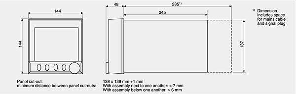
SIREC DM, dimensions
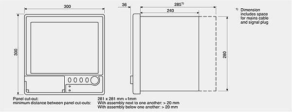
SIREC DH, dimensions
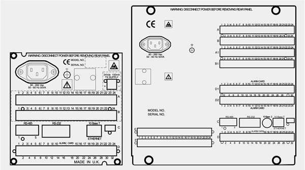
AC rear of SIREC DM (left) and SIREC DH (right) |
Схема подключения |
Дальнейшая информация |
Заказные данные
| Заказной № | Описание | Вес (кг) | Доставка | Мин. зак. (шт) |
| 7ND4421-.....-.... | ЦИФРОВОЙ ДИСПЛЕЙНЫЙ САМОПИСЕЦ SIREC D300, ФРОНТАЛЬНЫЕ РАЗМЕРЫ 144 X 144 MM, ДЛЯ ВСЕХ СТАНДАРТНЫХ ПРИЛОЖЕНИЙ, МИН. ЧАСТОТА ОПРОСА: 200 МС ДЛЯ MA,V,MV; ЗАДНЯЯ СТОРОНА КОРПУСА: ИНТЕРФЕЙС ETHERNET; RS485; USB-ИНТЕРФЕЙС, НА ЛИЦЕВОЙ ПАНЕЛИ: РАЗЪЕМ ДЛЯ КАРТО | 3.3 | по запросу (D) | 1 |
| 7ND4461-.....-.... | ЦИФРОВОЙ ДИСПЛЕЙНЫЙ САМОПИСЕЦ SIREC D400, ФРОНТАЛЬНЫЕ РАЗМЕРЫ 300 X 300 MM, ДЛЯ ВСЕХ СТАНДАРТНЫХ ПРИЛОЖЕНИЙ, МИН. ЧАСТОТА ОПРОСА: 200 МС ДЛЯ MA,V,MV; ЗАДНЯЯ СТОРОНА КОРПУСА: ИНТЕРФЕЙС ETHERNET; RS485; USB-ИНТЕРФЕЙС, НА ЛИЦЕВОЙ ПАНЕЛИ: РАЗЪЕМ ДЛЯ КАРТОЧ | 8 | по запросу (D) | 1 |
|
Аксессуары
| Заказной № | Описание | Вес (кг) | Доставка | Мин. зак. (шт) |
| 7ND4800-8BA | SIREC D ПРОГРАММНОЕ ОБЕСПЕЧЕНИЕ ОПЦИИ АКТИВИЗАЦИИ SIREC D-MANAGER PRO (ТРЕБУЕТСЯ УКАЗАТЬ НОМЕР РЕГИСТРАТОРА) | 0.1 | 6 - 8 недель (C) | 1 |
| 7ND4800-8CA | SIREC D АКТИВИЗАЦИЯ SIREC D-SERVER PRO(ТРЕБУЕТСЯ УКАЗАТЬ КОД БАЗОВОЙ ПРОГРАММЫ) | 0.1 | 6 - 8 недель (C) | 1 |
| 7ND4800-8EA | SIREC D SOFTWARE: UPGRADING OF SIREC D-MANAGER TO SIREC D SERVER | 0.1 | 6 - 8 недель (C) | 1 |
| 7ND4801-8AC | ОПЦИИ МИКРОПРОГРАММНОГО ОБЕСПЕЧЕНИЯ ДЛЯ SIREC D300 / SIREC D400, 10 КРЕДИТОВ | 0.1 | 6 - 8 недель (C) | 1 |
| 7ND4801-8BC | ОПЦИИ МИКРОПРОГРАММНОГО ОБЕСПЕЧЕНИЯ ДЛЯ SIREC D300 / SIREC D400, 20 КРЕДИТОВ | 0.1 | 6 - 8 недель (C) | 1 |
| 7ND4801-8CC | ОПЦИИ МИКРОПРОГРАММНОГО ОБЕСПЕЧЕНИЯ ДЛЯ SIREC D300 / SIREC D400, 30 КРЕДИТОВ | 0.1 | 6 - 8 недель (C) | 1 |
| 7ND4801-8DA | SIREC D SOFTWARE, ACTIVATION SIREC D-DESIGNER (NEW) | 0.1 | 6 - 8 недель (C) | 1 |
| 7ND4801-8DC | ОПЦИИ МИКРОПРОГРАММНОГО ОБЕСПЕЧЕНИЯ ДЛЯ SIREC D300 / SIREC D400, 40 КРЕДИТОВ | 0.1 | 6 - 8 недель (C) | 1 |
| 7ND4801-8EC | ОПЦИИ МИКРОПРОГРАММНОГО ОБЕСПЕЧЕНИЯ ДЛЯ SIREC D300 / SIREC D400, 50 КРЕДИТОВ | 0.1 | 6 - 8 недель (C) | 1 |
| 7ND4801-8FC | ОПЦИИ МИКРОПРОГРАММНОГО ОБЕСПЕЧЕНИЯ ДЛЯ SIREC D300 / SIREC D400, 60 КРЕДИТОВ | 0.1 | 6 - 8 недель (C) | 1 |
| 7ND4801-8GC | ОПЦИИ МИКРОПРОГРАММНОГО ОБЕСПЕЧЕНИЯ ДЛЯ SIREC D400, 70 КРЕДИТОВ | 0.1 | 6 - 8 недель (C) | 1 |
| |
|


