|
Inputs
|
|
Thermocouples to DIN IEC 584
|
Type
|
Measuring range
|
Error
|
|
L
|
0 °C ... 900 °C
|
≤ 2 K
|
|
J
|
0 °C ... 900 °C
|
≤ 2 K
|
|
K
|
0 °C ... 1350 °C
|
≤ 2 K
|
|
N
|
0 °C ... 1300 °C
|
≤ 2 K
|
|
S
|
0 °C ... 1760 °C
|
≤ 3 K
|
|
R
|
0 °C ... 1760 °C
|
≤ 3 K
|
|
T
|
-200 °C ... 400 °C
|
≤ 2 K
|
|
W
|
0 °C ... 2300 °C
|
≤ 2 K
|
|
E
|
0 °C ... 1000 °C
|
≤ 2 K
|
|
Display in
|
°C or °F
|
|
Input resistance
|
≥ 1 MΩ
|
|
TC break monitor, built in
|
Monitoring current ≤ 1 µA; configurable output action
|
|
Polarity monitoring
|
Responds when input signal is 30 K below span start temperature compensation: built in sensor or compensating leads must be taken up to the controller terminals.
|
|
Additional error
|
≤ 1 K / 10 K change of terminal temperature
|
|
Permissible DC voltage between inputs
|
1 V DC
|
|
Permissible AC voltage
- between inputs
- between inputs and ground
|
2 V AC
5 V AC
|
|
Resistance thermometer Pt 100 Ω to DIN IEC 751
|
|
Range
|
- 100.0 °C ... + 850.0 °C
|
|
With linearization (temperature linear)
|
≤ 2 K
|
|
Connection in three-wire technique without lead adjustment. With two-wire connection, a calibrating resistor equal to the lead resistance must be fitted.
|
Lead resistance : ≤ 30 Ω
Sensor current: ≤ 0.3 mA
Input circuit monitoring for break in sensor or lead, or short circuit. Configurable output action.
|
|
Direct voltage
Input span scalable via measurement correction.
|
0 mV ... 100 mV linear
Input resistance: ≥ 1 MΩ
Error: ≤ 0.1%
|
|
Scanning frequency
|
With thermocouple or Pt 100 input, all 8 inputs are scanned within 625 ms.
|
|
Current outputs
|
Range: 0/4... 20 mA configurable
Resolution: 10 bits
Accuracy: typ. ± 0.2% ± 1 digit
|
| |
Load impedance: max. 470 ohms
|
| |
Settling time: max. 625 ms
|
|
Constant voltage source
|
10 V ± 0.2%
|
| |
Load: max. 40 mA short-circuit protection, no sustained short-circuit protection
|
| |
The constant voltage source is galvanically isolated
|
|
Relay output
|
Floating changeover contact
Switching capacity: 24 V, 2 A
readback capability
|
| |
When used to calibrate strain gauges (inertial pressure), the relay must not be loaded with more 2 mA.
|
|
Digital input for controlling the relay
|
24 V DC external
Current sink (IEC 1131 type 1)
Galvanically isolated
|
|
Current transformer
|
Input range: 0 mA ... 30 mA AC
Ri approx.: 170 Ω; (e. g. for 0 A ... 30 A/ 0 mA ... 30 mA AC standard current transformer)
|
|
Digital inputs
|
The 4 digital inputs can also be configured as digital outputs. Galvanic isolation via opto-couplers. The digital inputs are galvanically isolated from the other temperature inputs.
|
|
Rated voltage
|
24 V DC external
Current sink (IEC 1131 type 1)
|
|
Logic ”0”
|
-3 V ... 5 V
|
|
Logic ”1”
|
15 V ... 30 V
|
|
Current requirement, approx.
|
5 mA
|
|
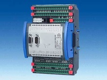
Digital interface KS800-DP
|
Stand-alone temperature controller with integrated PROFIBUS-DP interface and PROFIBUS-DP protocol.
|
|
Interface for PC and remote operation
|
An additional serial interface is provided for connecting the PC-based engineering tool, which is used for remote configuration, parameter setting and operation of the KS 800. A simple operator unit can be connected using the same (UART) interface.
|
|
Logic outputs
The outputs are scanned cyclically to check for short circuits or other faults.
|
12 logic outputs are available for direct connection of solid-state relays. If required, 4 digital inputs can also be configured as digital outputs. In addition, 3 outputs are available for alarm signalling.
|
|
Outputs, short circuit proof
|
24 V; switched (grounded load)
|
|
Nominal range of switched output voltage
|
18 V ... 30 V DC to DIN 19 240
|
|
Nominal output current
|
≤ 70 mA
|
|
Voltage drop across output at full load
|
0.6 V typical, 1 V max.
|
|
Power supply
|
24 V DC (+24V, gnd) protection class III (protective low voltage)
|
|
Nominal range
|
18 V ... 30 V DC
|
|
Power consumption, approx.
|
5 W
|
|
Control characteristics configurable as:
|
Control output: 0% ... 100% duty cycle
|
| |
- Signaller with 1 or 2 outputs
|
| |
- Two-point controller with DPID behavior
|
| |
- Three-point controller with DPID/DPID behavior
|
| |
- Three-step controller with DPID/DPID behavior and output algorithm for water vapor cooling (extrusion)
|
| |
- Positioner function with manual operation of three-point controller
|
| |
- Three-point stepping controller
|
| |
|
|
Control parameters
|
Self-tuning or adjustable.
Switching difference signal unit: 0.2%
|
|
Alarm functions
Output (logic output or interface) follow-on alarm signals from any control channels
|
- Relative or absolute measured value alarm
|
- Relative measured value alarm with alarm suppression
|
|
|
|
|
|
|
|
Heating current monitored through external current converter
|
See accessories
|
|
Heating current measurement
|
- e. g. transformer rating 30 A/30 mA AC
|
- For smaller heating currents, the load cable can be looped through the transformer several times for higher display accuracy, e.g. 2 x 15 A/30 mA AC.
|
|
Representation range (= scaling of measured current to actual current)
|
Selectable: 1.0 A ... 99.9 A so that other current transformers can be used
|
|
Measuring error
|
± 5% of display range
|
|
Heating current limit
|
Adjustable within selected display range, acting on an alarm output
|
|
Monitoring of undercurrent or short-circuit of the actuator
Response threshold of the short-circuit monitor
|
≥ 3% of selected range (with range 30.0 A: ≥ 0.4 A)
|
|
Set point
|
Upper and lower limits of the setpoint range are selectable within the measuring range limits.
|
|
Displays
|
- Status LEDs for ‘module OK’
|
- Status LEDs for ‘communication OK’
|
- LEDs for switching status. LED lights if input or output is active (high).
|
|
Program memory
|
EEPROM
|
|
Permissible temperatures
|
|
|
|
0 °C ... 55 °C
|
|
|
0 °C ... 60 °C
|
|
|
- 20 °C ... 60 °C
|
|
Climatic category KUF to DIN 40040
|
Relative humidity: ≤ 75% yearly average, no condensation
|
|
Auxiliary power
|
No influence. If the auxiliary power fails, there is no loss of configuration data (EEPROM storage)
|
|
Shock and vibration
|
|
Vibration test Fc to DIN 68-2-6
|
10 Hz ... 150 Hz
|
|
|
1 g or 0.075 mm
|
|
|
2 g or 0.15 mm
|
|
Shock test Ea nach DIN IEC 68-2-27
|
15 g, 11 ms
|
|
Electromagnetic immunity
|
Complies with EN 50082-2
|
|
Electrostatic discharge IEC 801-2
|
Air discharge: 8 kV
Contact discharge: 4 kV
|
|
Electromagnetic HF field
ENV 50140 (IEC 801-3)
|
80 MHz ... 1000 MHz, 10 V/m
|
|
Conducted high frequency
ENV 50141 (IEC 801-6)
|
0.15 MHz ... 80 MHz, 10 V
Influence ≤ 13 K; no influence with shielding
|
|
Fast pulse trains (burst)
IEC 801-4
|
2 kV applied to leads for supply voltage and signal leads
|
|
Electromagnetic radiation
|
Complies with EN 50081-2
|
|
Housing dimensions (W x L x H)
|
124 mm x 170 mm x 85 mm
|
|
Degree of protection to DIN 40050/IEC 529
|
Housing: IP20
Terminals: IP00
|
|
Approvals
|
UL-listed, CSA approval
|
|
CE marking
|
Fulfils the European Directives for electromagnetic compatibility and low voltage.
|
|
Electrical safety tested to VDE 0411
|
Protection class III (protective low voltage)
|
|
Electrical connections Phoenix type
|
FRONT-MSTB, 2,5/18ST-5,08
|
|
Mounting method
|
Can be snapped onto standard DIN rail (DIN EN 50022)
|
|
Weight, approx.
|
0.65 kg
|